
ASCENT-1
The first autonomous unmanned aircraft designed, integrated, and flight-tested by KFUPM ASCENT for the SUAS 2026 competition.
Engineering ASCENT-1
Payload & Release Mechanism
Custom system that drops both the beacon and bottle.
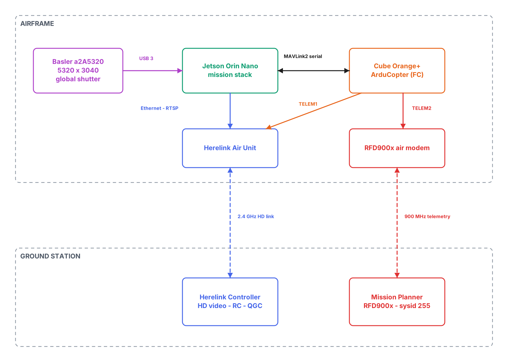
Jetson Nano
Companion computer running mission software in a custom 3D enclosure.
GPS Module
High precision GNSS receiver for autonomous navigation.
Herelink Air Unit (HAU)
Digital link carrying telemetry, and video to the GS.
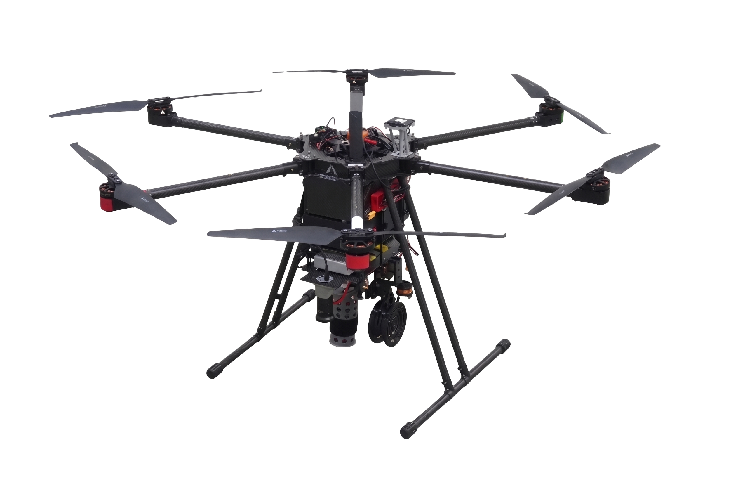
Vision Camera
Primary vision sensor for aerial object detection.
Cube Orange+
ArduPilot autopilot handling navigation, and waypoints.
Carbon Fiber Frame
Lightweight carbon fiber airframe — rigid at low weight.
Custom Battery Box
Enclosure for our upgraded power and quick battery swaps.
Our Vehicle — Documentation
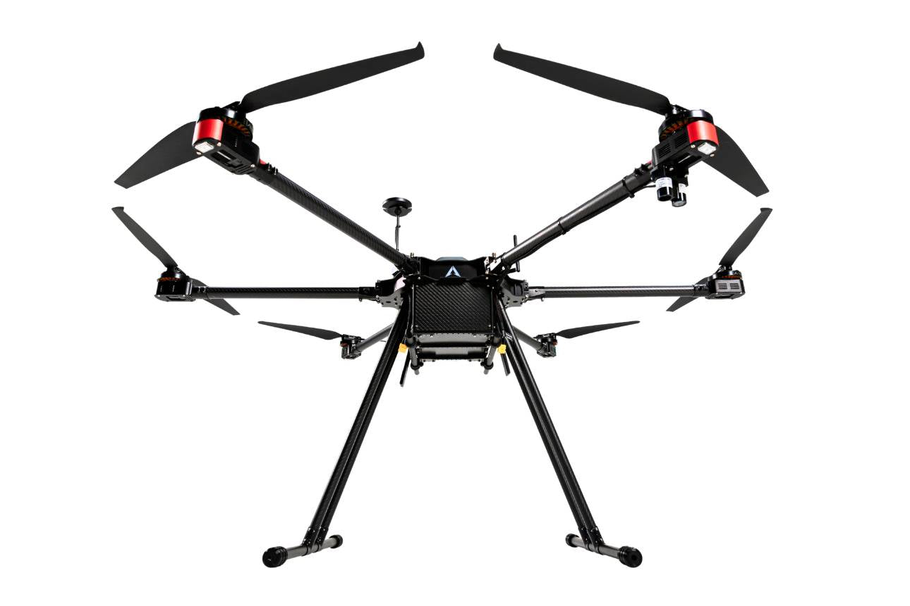
carbon-fiber heavy-lift hexacopter.
Technical Specifications
Dimension Drawing
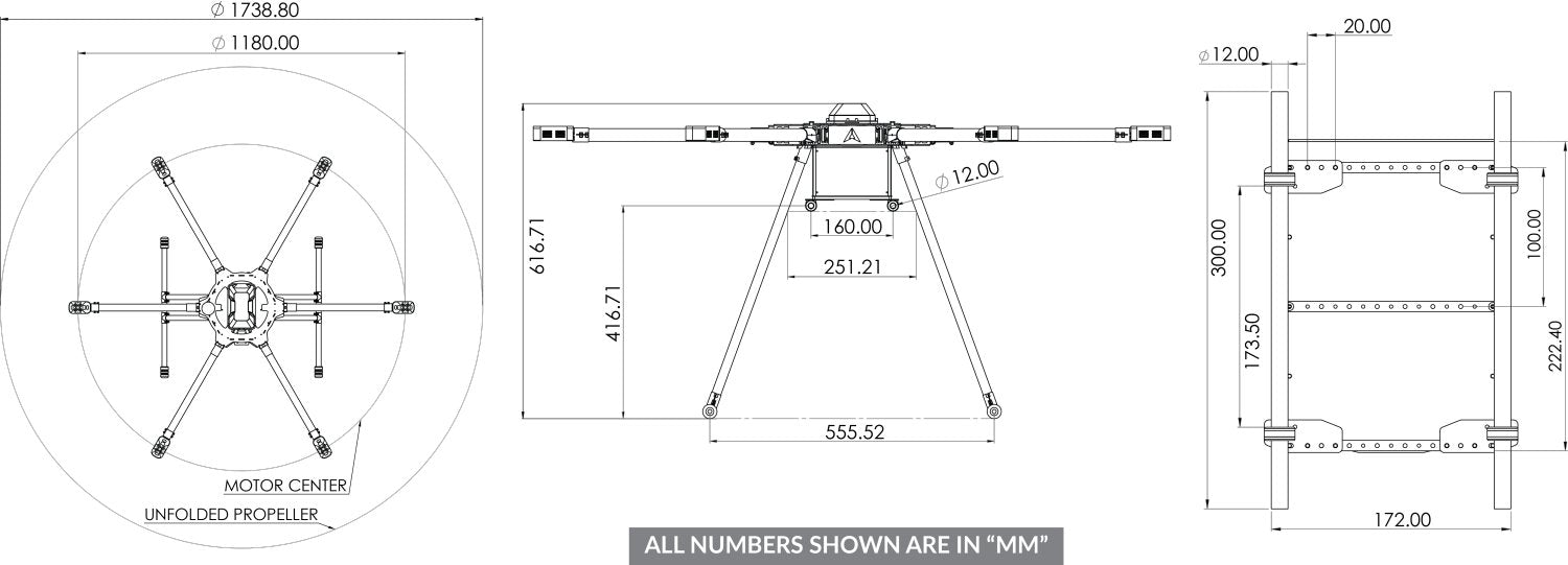
Dimension drawing, values in mm: wheelbase Ø1180 · unfolded Ø1738.8 · height 616.71 · landing-gear span 555.52 · payload plate 300 × 172.
Orthographic Views
Front elevation
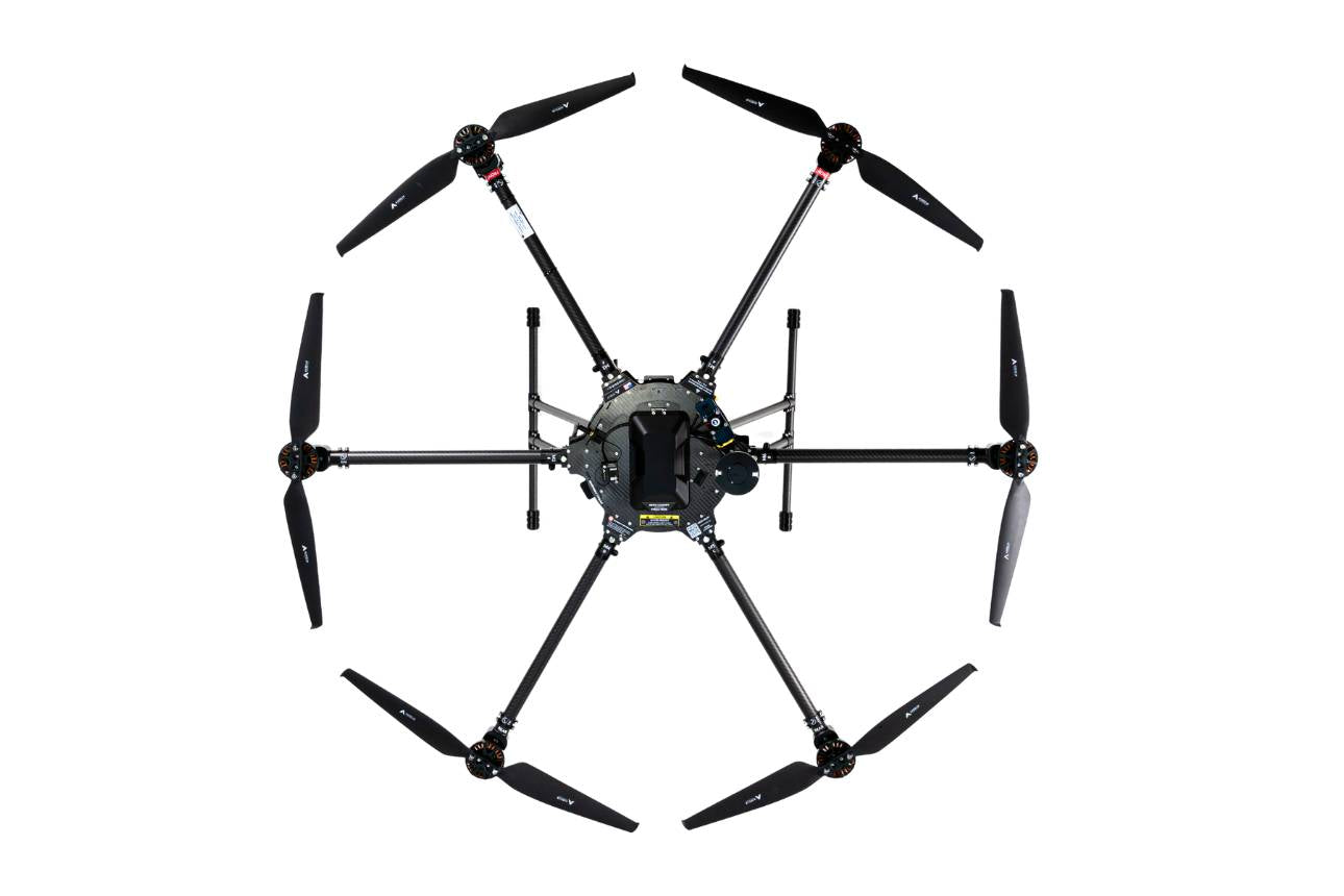
Top plan
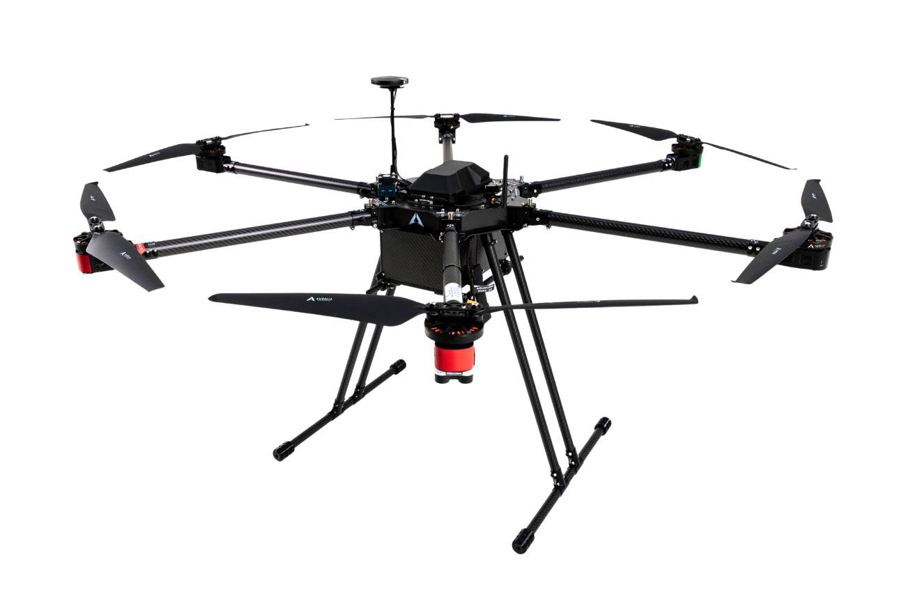
Isometric
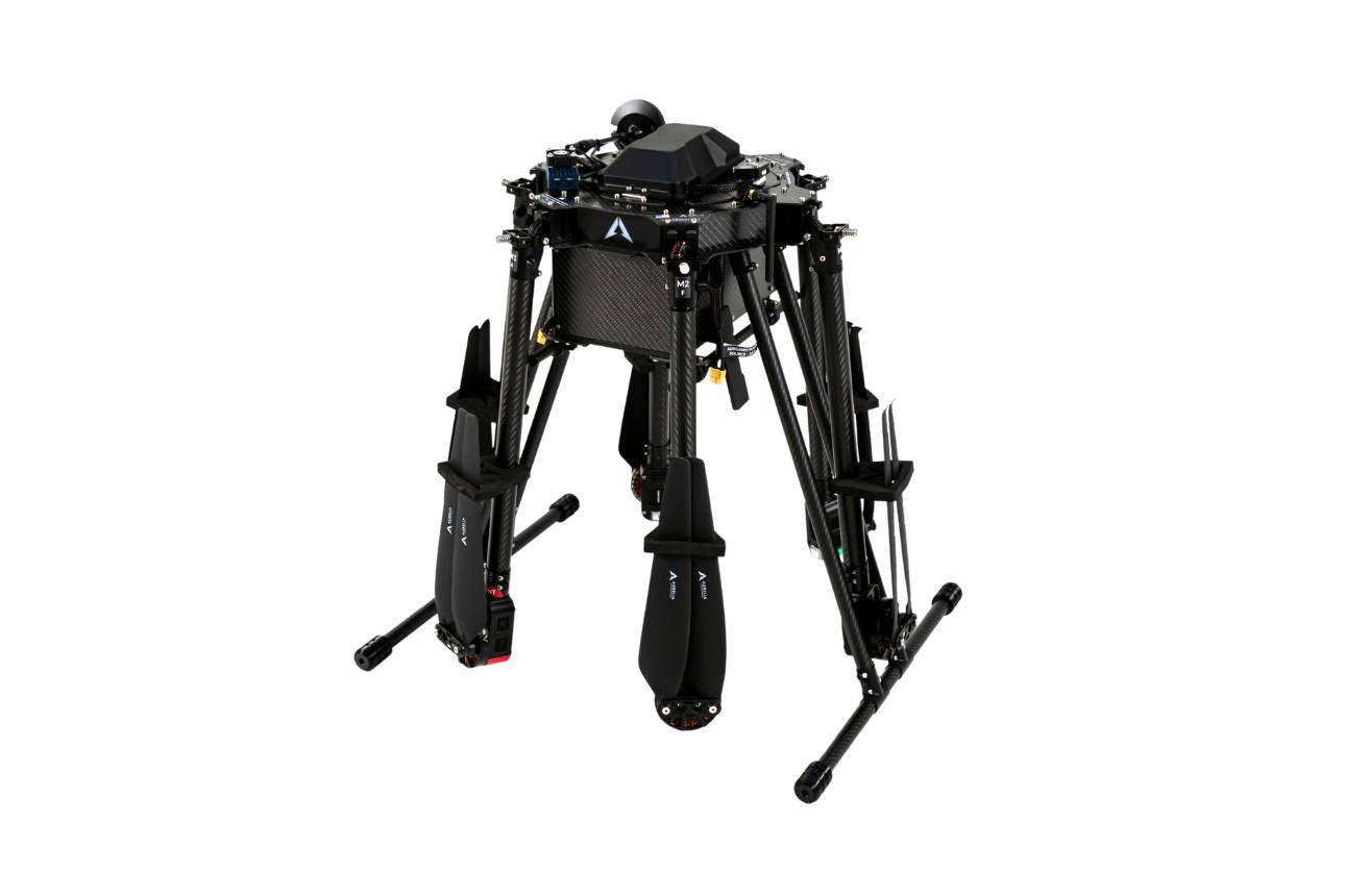
Folded (transport)
Subsystems & Components
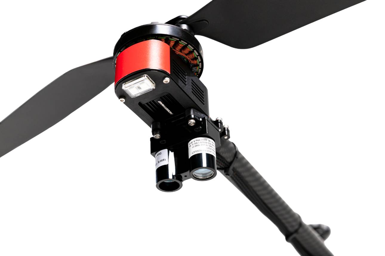
Downward LiDAR rangefinder
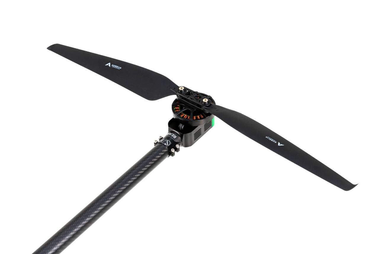
Folding propellers
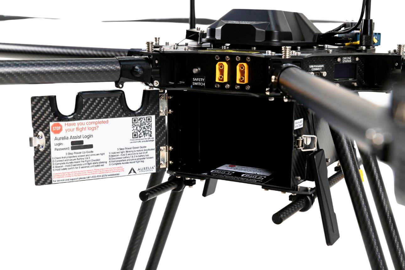
Dual-battery bay
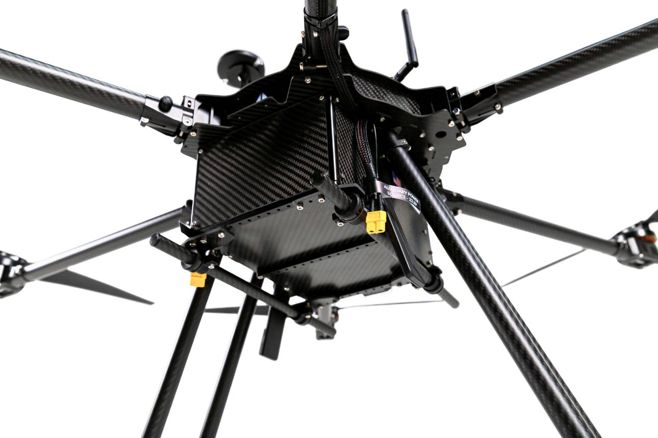
Payload connection tubes
Aircraft Specifications
Values drawn from the team's own integration and testing are final; rows marked. Competition limits are per the SUAS 2026 rules.
Watch Our Proof of Flight Readiness
This footage shows ASCENT-1 performing controlled flight during the team's preparation for the SUAS 2026 competition — a demonstration of the airframe's airworthiness and the flight stack's readiness ahead of full autonomous missions.
Engineering Subsystems
From a Detection to a Ground Coordinate
A YOLO box only says where a target sits in the image. To act on it, ASCENT-1 has to know
where the target is on the ground. This pipeline — the real one behind our test report
(PoseBuffer → pixel_to_ground → estimator → closed-loop hover) —
turns a pixel into a geographic coordinate, flies over it, and refines the estimate in a hover.
Observe
Gimbal camera frame stamped against a buffer of timestamped aircraft poses.
Detect
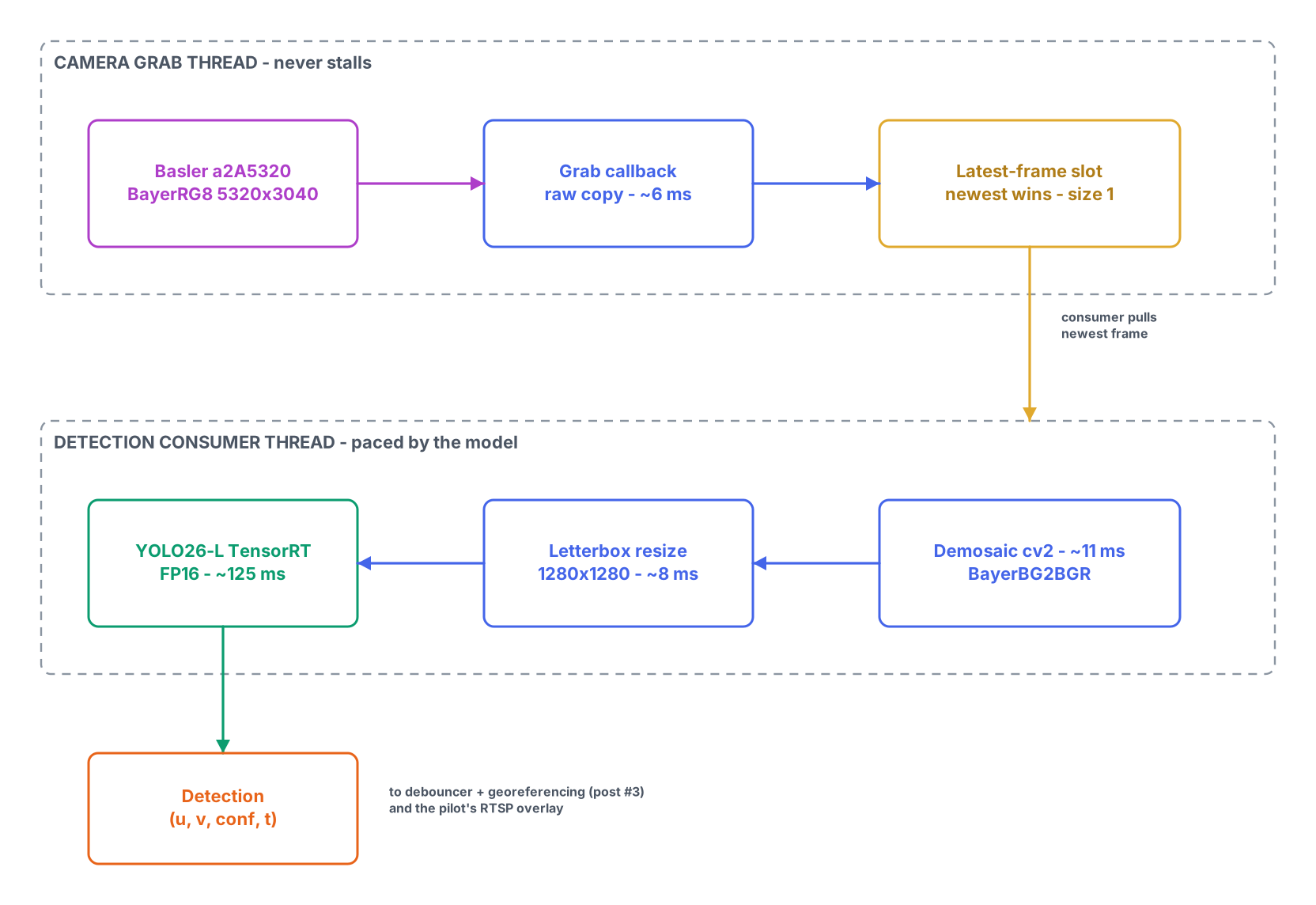
On-board detection returns the target's pixel bounding box.
Project
The box-centre pixel ray is intersected with the ground plane using pose + intrinsics.
Estimate
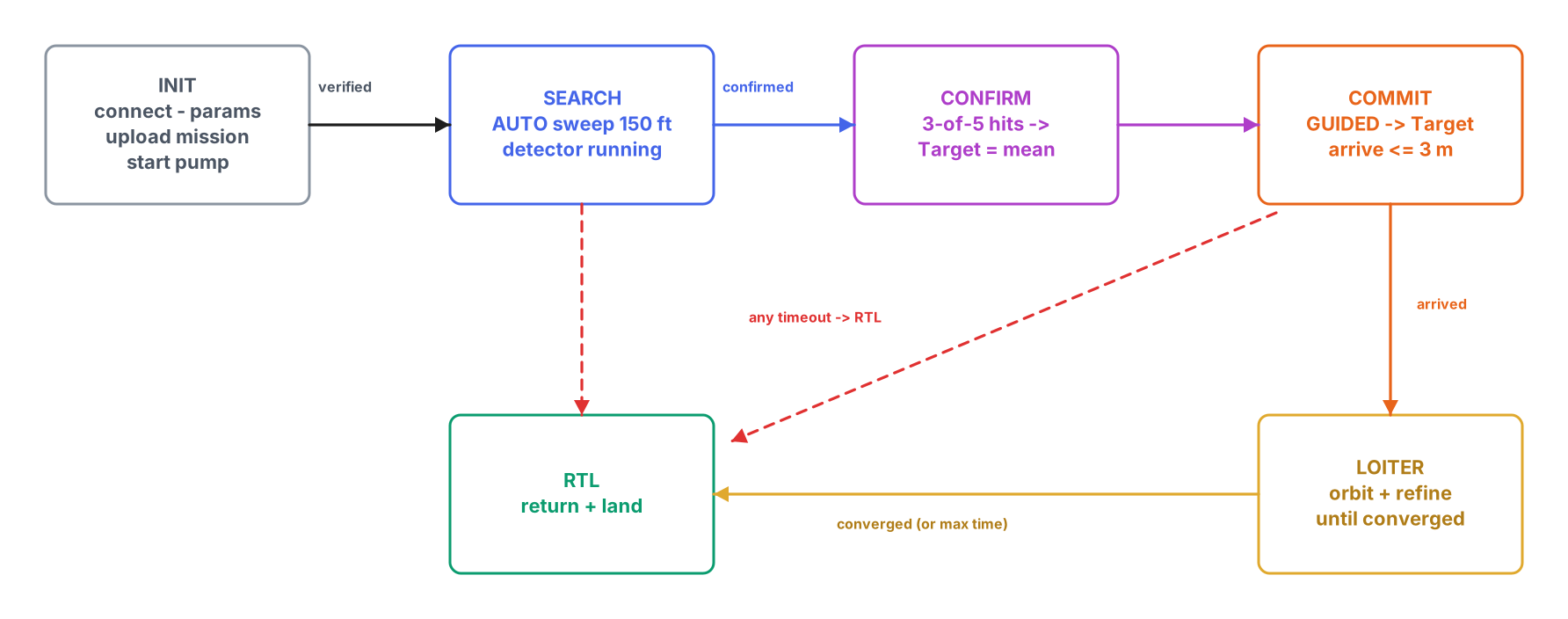
Geolocated samples are fused into one lat/lon at CONFIRM.
Reposition
The drone flies over the estimate and refines it while holding station.
Each tab replays one recorded simulation trial for a different defect. Watch the drone fly the lane past the object (red ✚), green geolocated detections land, the yellow estimate settle, then the view zoom in for the 60 s hover — where the estimate either walks onto the object, or (for camera tilt) refuses to.
The scenarios are the ones the team actually tested: a clean baseline, a wrong field-of-view calibration, a 2° camera tilt, and a realistic combination of clock lag, FOV error and tilt.
The math is exact
A 12-combination yaw/offset round-trip unit test recovers the object to under 1 mm. With clean inputs the live estimate lands within a centimetre.
The hover erases FOV error
A 20%-wrong field of view biases the sweep estimate — but hovering with the object at image centre makes intrinsics barely matter, and the error collapses.
Tilt is what survives
A tilted camera biases every sample identically, so averaging can't remove it. Error = altitude·tan(tilt): 6.4 m at 12° off nadir. Lock the gimbal 90° down.
Where it sits in ASCENT-1
Read Our Team Design Report
This page is a condensed summary of one subsystem. The full engineering detail for ASCENT-1 — requirements, analysis, testing, and results across every subsystem — lives in the team's official Team Design Report submitted to the AUVSI SUAS 2026 competition. The complete report is embedded below.
If the embedded viewer does not load on your device, use Open Full Report to read the PDF in a new tab.