
Power Systems
The lithium-ion battery architecture, power distribution, and validated energy model that give ASCENT-1 its endurance.
Overview
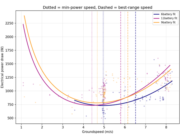
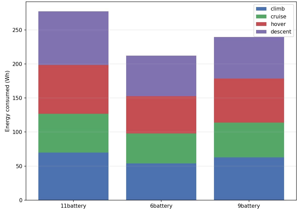
The Power Systems subsystem provides and distributes every watt on ASCENT-1 and predicts how long the aircraft can fly. The team selected a lithium-ion main pack for its energy density and sized the configuration by modelling energy consumption across the real phases of a mission — climb, cruise, hover, and descent.
A second constraint shaped the design: the competition's easy-to-transport battery rule caps the energy of any single pack, which pushed the team toward several smaller packs wired together rather than one large battery.
Engineering Objectives
- Deliver the endurance the SUAS mission needs within the aircraft's weight budget.
- Keep every battery pack within the competition's transport energy limit.
- Distribute clean, regulated power to the flight, avionics, and payload domains.
- Predict mission energy accurately enough to plan flights with confidence.
Major Components
Lithium-ion main battery
A multi-pack configuration selected after modelling energy use across flight phases.
External + main power distribution boards
Two-stage distribution feeding the six ESCs on the 24 V main bus.
5V/12V UBEC
Regulated rails for the avionics and companion electronics.
Separate 12 V payload battery
An isolated supply for the payload-release mechanism.
Energy model
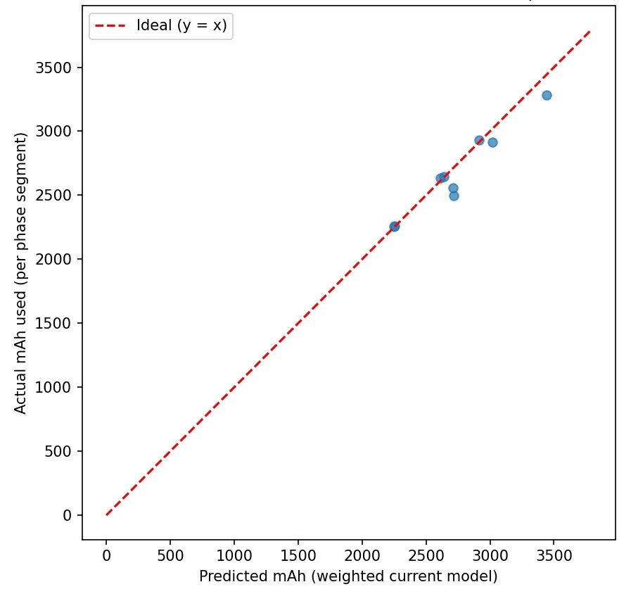
A per-phase current model validated against real flight measurements.
Transport-compliant packs
Individually sized to stay under the competition's energy limit for shipping.
Integration with ASCENT-1
Power feeds every other subsystem: the ESCs and motors of Autonomous Flight, the Jetson and camera of AI & Communication and Computer Vision, and the payload release of Payload Systems — each on an appropriate regulated rail.
The validated energy model feeds Mission Planning, giving an up-front estimate of how much battery a given route and payload will need and supporting autonomous endurance decisions in flight.
Subsystem Architecture
Engineering Gallery
Technical Highlights
Evidence-based sizing
The battery configuration was chosen by modelling energy per flight phase, not by intuition.
Transport-compliant
Multiple smaller packs keep each unit under the competition's energy limit for shipping.
Validated model
Predicted energy matches flight measurements closely, and errs high on the longest segments — the safe direction.
Isolated domains
Flight, avionics, and payload draw from separate regulated supplies.
- Add live battery-health telemetry to the pre-flight checklist.
- Fold temperature effects into the energy model for hot-day missions.
- Expand the model's flight-test dataset to tighten its confidence bounds.