
Wiring Up ASCENT-1: The Electrical Architecture
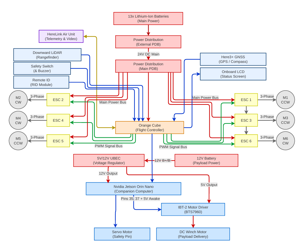
Today we finished mapping out the full electrical architecture of ASCENT-1 — the single diagram that shows how every component draws power and talks to the flight controller. With the battery choice already settled, this was the natural next step: turning a pile of parts into one coherent system on paper before a single wire gets crimped.
At the center sits the Orange Cube+ flight controller, fed navigation data by the Here3+ GNSS and linked to the ground through HereLink for telemetry and video. The lithium-ion main pack runs through an external and then a main power distribution board, which feeds the six motor ESCs on the main bus and steps down through a UBEC to the 12V and 5V rails that power the avionics. The Jetson Orin Nano rides alongside as the companion computer for the autonomy stack. One deliberate choice: the payload delivery winch runs off its own 12V battery through a dedicated motor driver, so lowering a payload never pulls current away from the flight-critical systems.
Laying it out this way also forces the safety and support pieces into the plan from the start — the safety switch, Remote ID, downward LiDAR, and onboard status display each have a defined place on the bus instead of being bolted on later. With the architecture agreed on, the next milestone is building it for real and integrating it onto the airframe.
Figures & Diagrams
Electrical Architecture Diagram
The full electrical architecture of ASCENT-1, mapping every subsystem onto the power and signal buses.